Step By Step Instruction, DIY (Do It Yourself) RC Hydraulic Excavator Upgrade Package For HuiNa 580 All Metal (Full Metal) RC Excavator. Leave a comment
Step By Step Instruction, DIY (Do It Yourself) RC Hydraulic Excavator Upgrade Package For HuiNa 580 All Metal (Full Metal) RC Excavator.
— How To Step By Step DIY Transform (Customize, Modify) Your Toy Excavator Into A Professional RC Hydraulic Excavator
- Click to buy: HuiNa 580 All Metal (Full Metal) RC Excavator.
- Click to buy: DIY RC Hydraulic Excavator Upgrade Package.
First step, You need to prepare the following tools.
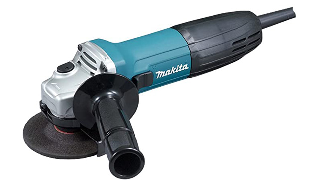
Angle Grinder
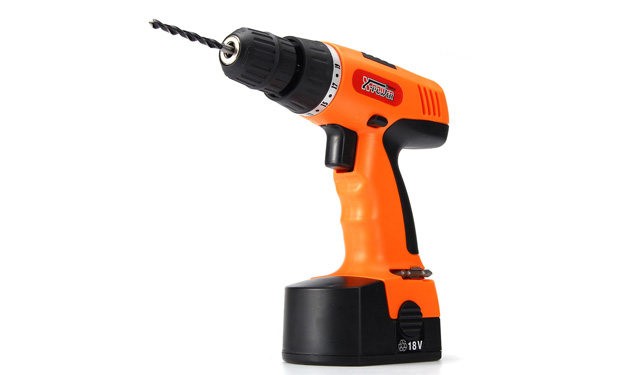
Electric drill
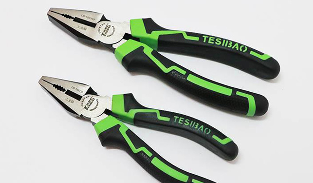
Flat-nose pliers
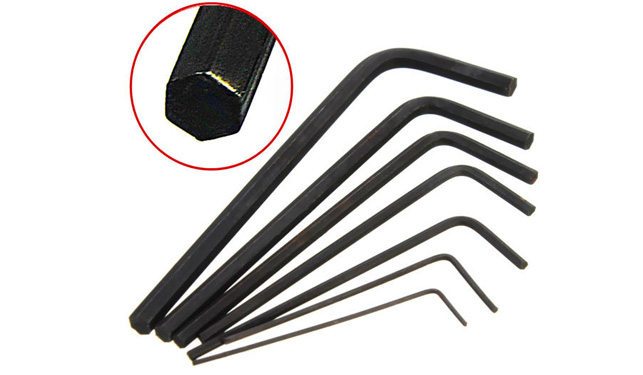
Hex Screwdriver
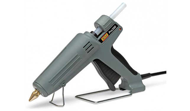
Hot Melt Glue Gun
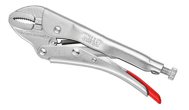
Locking pliers
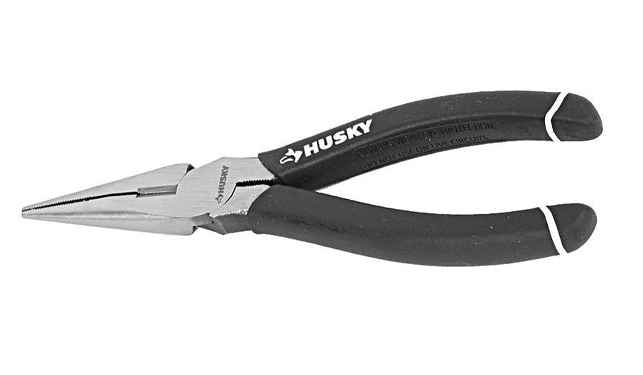
Needle nose pliers
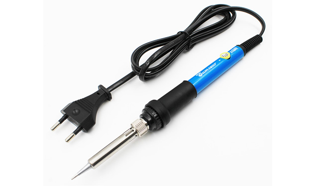
Solder Iron
Second step, how to open HuiNa 580 RC Excavator.
- There are 5 screws at the bottom of the body of the Hui-Na 580 RC Excavator. Upside down the 580 RC Excavator, Maybe you can find 3 screws on the bottom of the body. In order to find other screws, you need to turn the track chassis clockwise or counterclockwise (Maybe you need some force to rotate the crawler chassis).
https://youtu.be/rElsI4VXqds
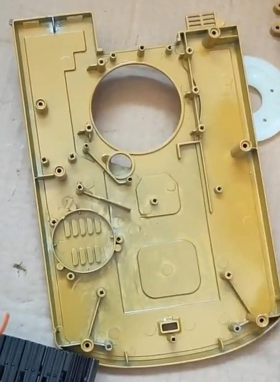
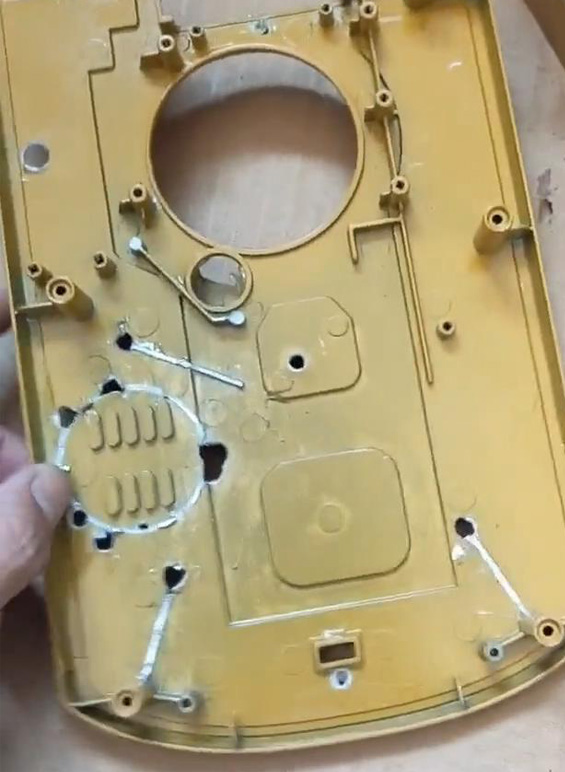
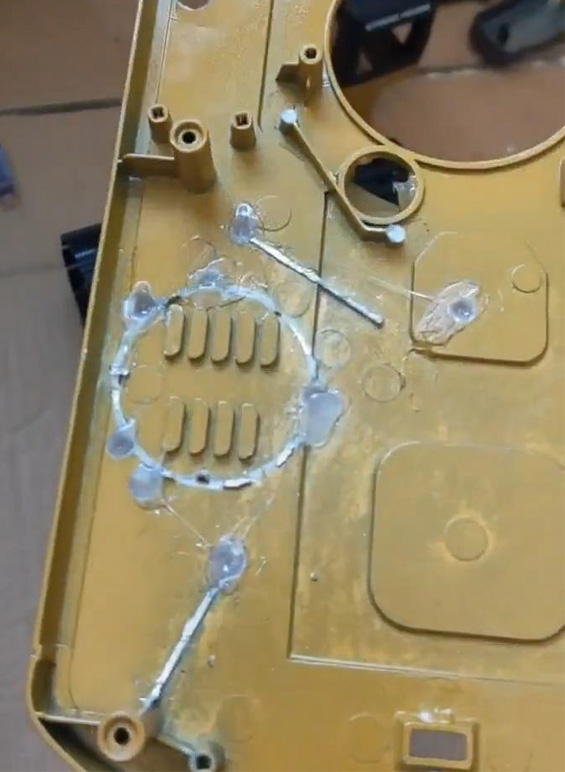
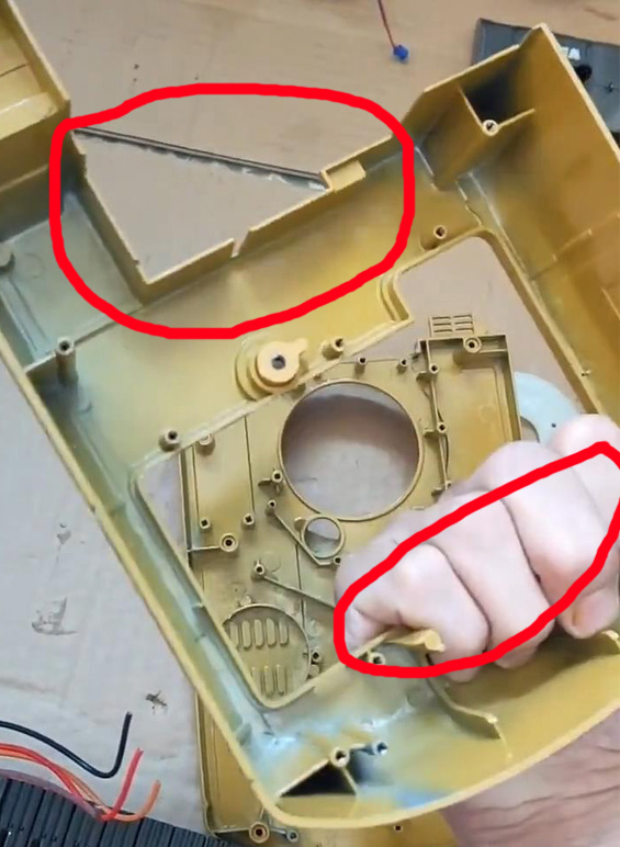
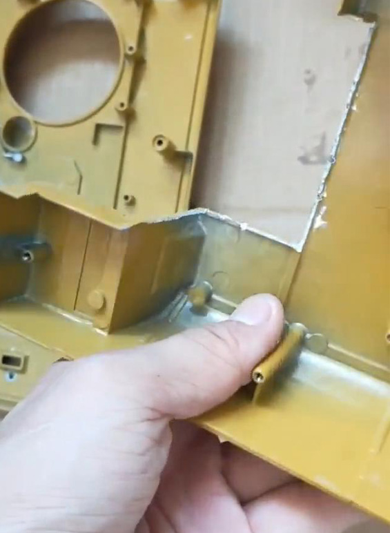
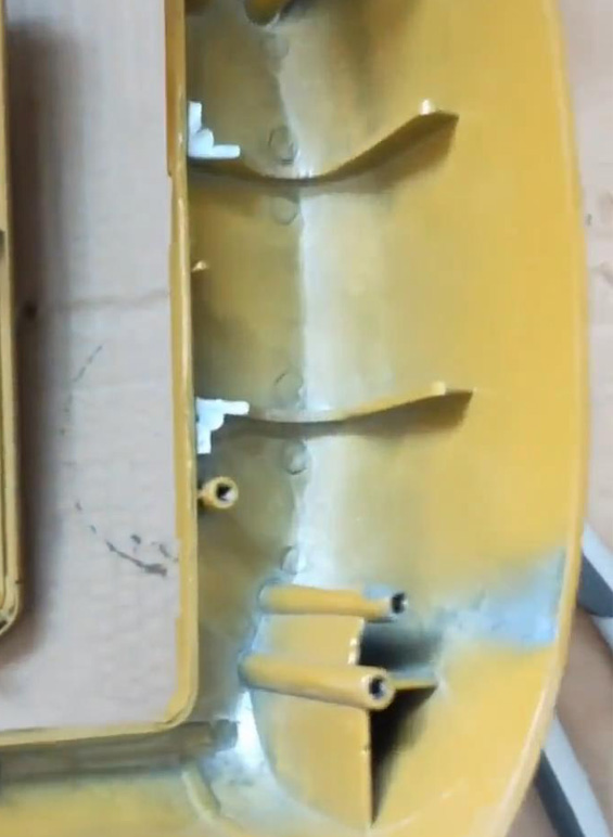
Third step, Reconstruct the HuiNa 580 body chassis, make it flat to install the hydraulic system.
- Tools needed: Angle Grinder, Flat-nose pliers, Hot Melt Glue Gun, Locking pliers, Needle nose pliers.
Original body bottom
Flattened body bottom
Hot melt adhesive filling
Original Upper body
After cutting
After cutting
The Fourth step, Drilling Holes. the Fluid (Hydraulic) Directional control valves (DCVs) need 2 * ø2.5mm holes for mounting. also need 15 * ø5mm cooling holes for Heat dissipation.
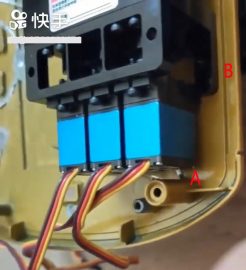
- installation the Hydraulic Directional control valves, It is recommended to use 2 nuts to raise it. Click to view demo.
- Please note: Before fixing the Directional control valves, the inlet / outlet of the Directional control valves must be connected with hydraulic oil transmission pipeline. Click to view demo.
about the fixed position of the Directional control valves. A about 5mm. B about 8mm.
The fifth step, Install the excavator hydraulic boom arm.
- The excavator hydraulic boom arm has been assembled 100% (contain, excavator boom, boom hydraulic cylinders; excavator stick (arm), stick (arm) hydraulic cylinders; bucket, bucket linkage, bucket hydraulic cylinders). It is fully adapted to the body of Hui-Na 580 RC Excavator. 7 screw holes match the screw position of the car body.
The sixth step, Install the excavator Hydraulic pump.
- Integrated hydraulic pump and hydraulic oil tank (hydraulic pump & hydraulic oil tank all in one). It has a built-in Relief valve (pressure relief valve (PRV)), The working pressure of the relief valve is 3MPA.
- Use double-sided tape to stick the metal weight blocks (the weight blocks is included in the order, double-sided tape not). How high should the counterweights be stacked? Refer to the base of the boom arm, 0 ~ 4mm.
- Use double-sided tape to stick the “Integrated hydraulic pump and hydraulic oil tank” to the weight blocks. 5mm should be reserved for the front, and 3mm should be reserved on the right side, for To install the cab housing shell. (hydraulic pump & hydraulic oil tank all in one) (cab housing with hydraulic pump installed)
Step 7, Commissioning the hydraulic pump.
- Connect the hydraulic pump brushless motor, ESC (Electronic speed control), remote control receiver. (How to connect electronic equipment, please refer to the instruction manual of the remote control, It is recommended to use a 10-channel remote control).
- It is correct that the brushless motor of the hydraulic pump rotates counterclockwise. ✔.
- If not, exchange 2 wires randomly.
https://youtu.be/ebKeSkPRt84
Step 8, Connect the hydraulic oil transmission pipeline.
- Connect hydraulic pump and the Fluid (Hydraulic) Directional control valves (DCVs).
- Connect Directional control valves and boom hydraulic cylinders; arm hydraulic cylinders; bucket hydraulic cylinders.
- note, the boom arm needs to be at the minimum working height.
- Directional control valves’s oil inlet (oil outlet), the upper and lower position is a group. There is No limit of special group must be connected to the specified hydraulic cylinder. But we must consider the beauty and reasonable layout. Recommended layout.
- The final control channel can be set by the remote controller.
Step 9, Connection circuit.
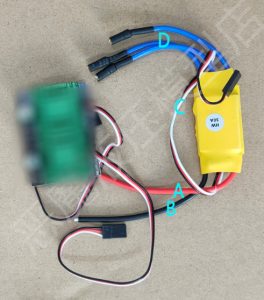
- hydraulic pump ESC Connection.
- A : positive electrode.
- C : Connect the receiver.
- B : negative electrode.
- D : connect Brushless motor of hydraulic pump.
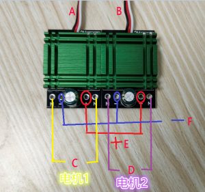
- “Excavator track drive” ESC Connection.
- A, B : Connect the receiver.
- E, F : Positive, Negative.
- C : Connect the Drive motor 1.
- D : Connect the Drive motor 2.
- note, the Excavator track drive ESC is Double Sided Printed Circuit Board. the Power supply connection diagram on the second side.
Step 10, The internal layout of electronic parts.
Step 11, Make it look more beautiful.
Step 12, Good job, done. 🙌

